This video just want to show our traffic vehicle detector function and the loop inductive can be identification if you want to use it for traffic control app.
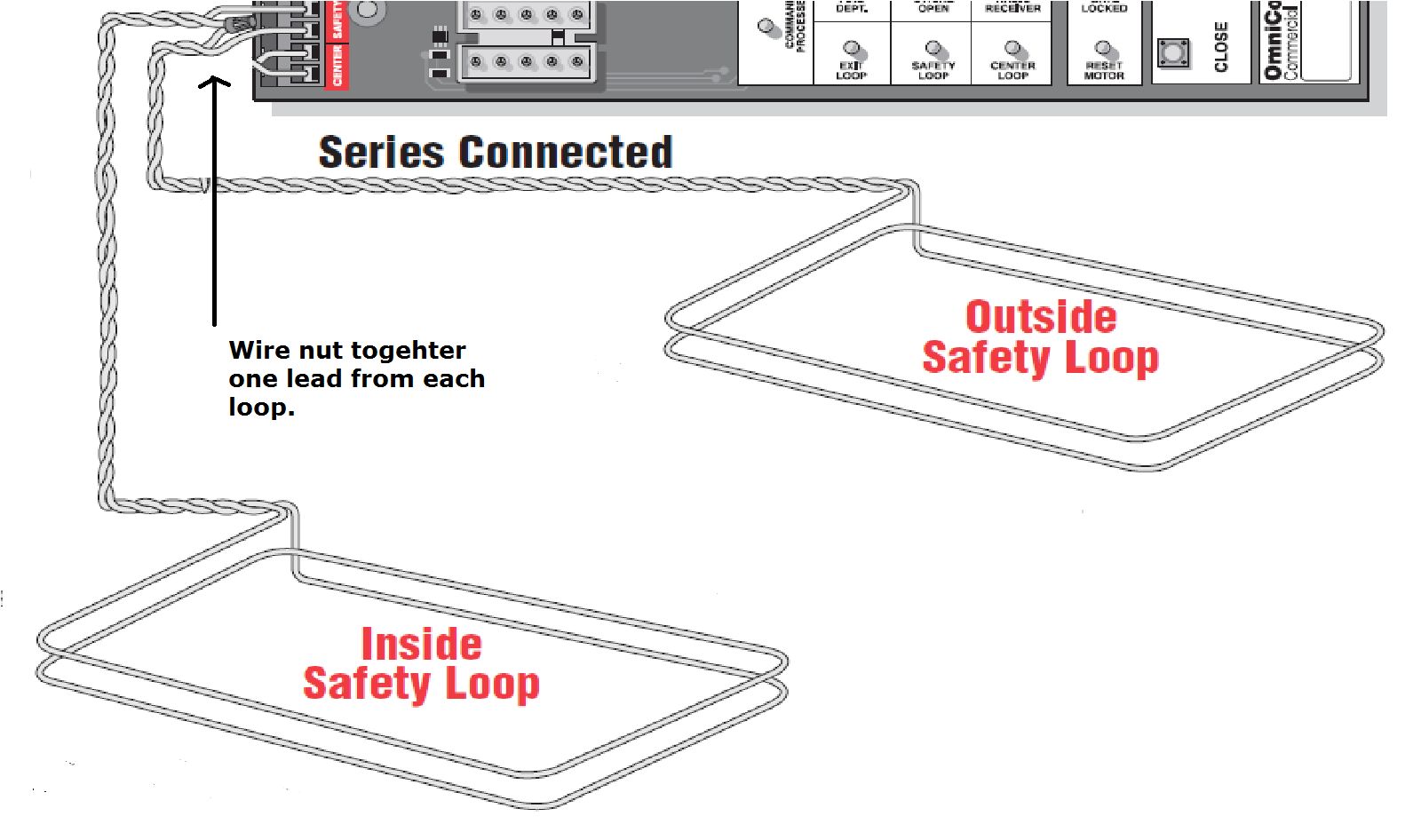
Vehicle detection loop detector wiring diagram.
Vehicle loops and loop detectors are used to detect the presence of a vehicle to open a gate or as a safety device to prevent the gate from closing on a vehicle in its path.
Nortech detection pty ltd tel.
In general loop vehicle detectors from all manufacturers work under the same principle and will all work reliably if the installation is done.
A buried coil of wire loop in the roadway vehicle detector electronic module.
The proper installation and material is critical.
To check leakage disconnect loop from detector.
An insulated electrically conducting loop is installed in the pavement.
It is shipped with a underwriters laboratories approved class 2 plug in the wall 12 vdc power adapter.
Basics of vehicle detection loops.
The incorrect type of wire will also leak to ground.
Vehicle detection if no response should be an increased sensitivity to stall so repeated several times until the car seized stability for normal work.
Vehicle detection loops called inductive loop traffic detectors can detect vehicles passing or arriving at a certain point for instance approaching a traffic light or in motorway traffic.
Since asphalt is more flexible than concrete it is recommended that a heavier gauge wire be used for loop installations in asphalt.
Use a multi meter to measure the resistance from one loop wire to ground stick long nail in dirt if operator does not have ground.
The marsh loop vehicle detector can be powered by either a 9 20vdc or 9 16vac.
The wire should maintain its integrity under the pavement stress.
02 9475 4742 email.
The electronics unit applies alternating current electrical energy onto the wire loops at frequencies between 10 khz to 200 khz.
3 wiring diagram pin designation 1 live 230v ac 50 60 hz 2 neutral 3 pulse relay normally open contact 4 pulse relay common contact 5 presence normally open contact 6 presence relay common contact.
Loop wire insulation and sealant.
The wire gauge is not critical to proper operation of the loop detector.
Be sure that other loop wire is floating not connected.
However the power can be supplied by any external device and connected via the screw terminals provided inside the enclosure.
In general direct burial loops are placed below the surface prior to application of asphalt or concrete while cut in loops are installed within a slot sawed into.