Nema ratings are standards that define the types of environments an electrical enclosure can be used in.
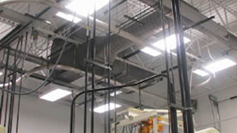
Vertical cable tray installation standards.
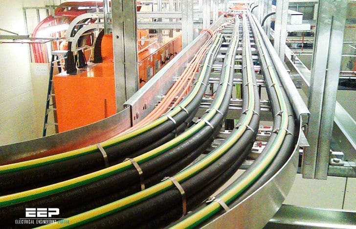
Sheaves or a shoe may be used to guide the cable into the tray.
Aluminum offset splice plate assembly.
Cable tray systems design shall comply with nec article 392 nema ve 1 and nema fg 1 and follow safe work practices as described in nfpa 70e.
New products vertical cable is proud to showcase the latest products for all your cable needs.
Following are the steps to be done for laying cables on wall mounted cable tray.
Vertical cable tray elbows at the bottom of runs should be supported at the top of the elbow and within 610mm of the joint at the bottom of the elbow.
Notice and disclaimer the information in this publication was considered technically sound by a consensus among persons engaged in its development at the time it was approved.
For cable tray installers this publication is intended as a practical guide for the proper installation of cable tray systems.
California florida new york.
Line card view vertical cable s line of products stocked in 3 locations.
2 4 straight cable ladder and cable tray lengths 29 2 5 coupler types refer to manufacturer s literature 32 2 6 fixings 36 2 7 fittings 36 2 8 accessories 39 2 9 site modification 39 2 10 earth protection and emc 40 2b.
Figure f 3 cable feed into cable tray d cable sheaves or a shoe may be used to guide cable into the desired direction maintain minimum bend radius and reduce friction.
Nema ve 1 this standard specifies the manufacturing requirements for metal cable trays such as.
Catalog download vertical cable s latest product catalog before placing an order today.
Electrical and industrial power management solutions eaton.
The size length and intervals of the support to be as per the specification standards.
Below drawing shows how to install cable tray and its support system.
Vertical cable tray elbows at the top of runs should be supported at the joint on each end.
This cable tray support system drawing has isometric view and cross sectional view.
Ve2 is a nema standard that outlines cable tray installation practices material control and unloading storage standards.
Installation of cable 41 2 11 preparation 41 2 12 wiring regulations 41 2 13 power cables 41 2 14 data cables 46 2 15.
Channel cable tray ladder cable tray single rail cable tray wire mesh cable tray solid bottom or nonventillated cable tray and trough or ventilated cable tray and associated fittings for use in accordance with the rules of the national electrical code.